

- #Mpu 6050 arduino camera gimbal generator#
- #Mpu 6050 arduino camera gimbal serial#
- #Mpu 6050 arduino camera gimbal software#
- #Mpu 6050 arduino camera gimbal code#
- #Mpu 6050 arduino camera gimbal free#
I2Cdev and MPU6050 must be installed as libraries, or else the.
#Mpu 6050 arduino camera gimbal software#
OUT OF OR IN CONNECTION WITH THE SOFTWARE OR THE USE OR OTHER DEALINGS IN LIABILITY, WHETHER IN AN ACTION OF CONTRACT, TORT OR OTHERWISE, ARISING FROM,

IN NO EVENT SHALL THEĪUTHORS OR COPYRIGHT HOLDERS BE LIABLE FOR ANY CLAIM, DAMAGES OR OTHER IMPLIED, INCLUDING BUT NOT LIMITED TO THE WARRANTIES OF MERCHANTABILITY,įITNESS FOR A PARTICULAR PURPOSE AND NONINFRINGEMENT. THE SOFTWARE IS PROVIDED "AS IS", WITHOUT WARRANTY OF ANY KIND, EXPRESS OR

The above copyright notice and this permission notice shall be included inĪll copies or substantial portions of the Software. To use, copy, modify, merge, publish, distribute, sublicense, and/or sellĬopies of the Software, and to permit persons to whom the Software isįurnished to do so, subject to the following conditions: In the Software without restriction, including without limitation the rights Of this software and associated documentation files (the "Software"), to deal
#Mpu 6050 arduino camera gimbal free#
Permission is hereby granted, free of charge, to any person obtaining a copy
#Mpu 6050 arduino camera gimbal code#
I2Cdev device library code is placed under the MIT license - fixed gyro sensitivity to be 2000 deg/sec instead of 250 - remove accel offset clearing for better results (thanks Sungon Lee) - add Euler output and Yaw/Pitch/Roll output formats - add 3D math helper file to DMP6 example sketch - add gravity-compensated initial reference frame acceleration output - fix broken FIFO read sequence and change interrupt detection to RISING - pull gyro and accel data from FIFO packet instead of reading directly - completely rearranged DMP initialization code and simplification - improved FIFO overflow handling and simplified read process - added note about Arduino 1.0.1 + Leonardo compatibility error - Eliminated a potential infinite loop - and altered FIFO retrieval sequence to avoid using blocking code
#Mpu 6050 arduino camera gimbal generator#
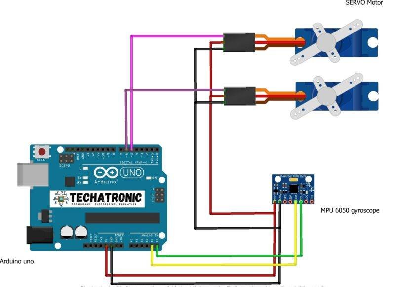
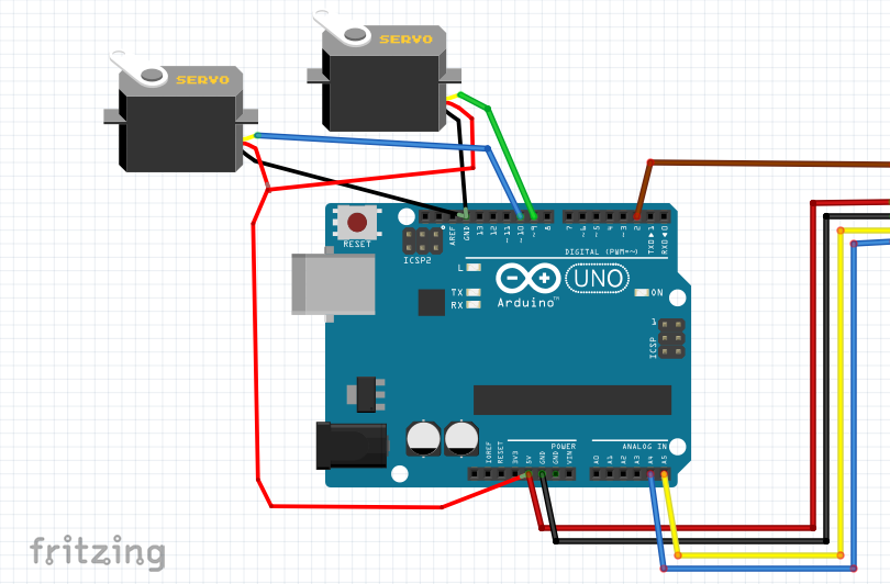
- Added Auto Calibration and offset generator Updates should (hopefully) always be available at I2C device class (I2Cdev) demonstration Arduino sketch for MPU6050 class using DMP (MotionApps v2.0) See attached photo and wiring diagram that I followed.
#Mpu 6050 arduino camera gimbal serial#
Good thing: I'm seeing absolute nonsense in the serial monitor. The data ouputted by the DMP is in quaternion format. As far as I know the only Arduino libraries that do this are ones based on Jeff Rowbergs work. As others have commented, youll want to grab data from the DMP because that is where the magic happens. Will eventually be outputting the data from an MPU6050 to an LCD screen, but wanted to check the sensor itself first. The MPU-6050 certainly measures orientation angles: yaw, pitch, roll. Here is the logs of what we got on Serial Port.Hey, everyone. * Clock Source: PLL with X axis gyroscope reference If our wiring and hardware is proper, we should get values of each axis on Serial port for both Raw and Normalized gyroscopic change in sensor. Once the upload is done, its time to open up the serial Monitor and observe output:ĭon’t forget to match the serial port with the baud rate we defined in start of code which is 115200 since our example code is ready and we understand what we did in code, its time to upload the code and view results.


 0 kommentar(er)
